airscapes
Elite Member
If you are reading this you may have already read my previous post about the Simple FM Transmitter I built. That worked great and still does, but I wanted another project and wanted to try a $30 FM transmitter Kit I had seen which is PLL and fully tunable across the complete FM band. For the receiver end, I use a small Walkman with a set of Etymotic in-ears
Here is a link to the BA1404 kit. http://electronics-diy.com/store.php?sel=kits&sub=fm_transmitters
This site does not respond to email, and I was kind of skeptical if I would get the kit and if it would be complete. Ordered it on a Friday, arrived the following Monday. Checked the parts list and all was accounted for. I did find out as I assembled it, on capacitor (C5) is not on the parts list but was present.
The instructions are one page, it assumes you have built kits before and have the basic skills to look a the board marking and the pictures that are included. It is not step by step.
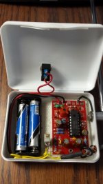
The only thing I ran into is that the carrier leaks a bit on this IC and causes a rolling sine wave tone that is rather annoying. The data sheet for the BA1404 IC talks about adding var pots to fix this, but a .001uf Disc Cap (code stamp 102) the + and - of one of the inputs ( I put it on the left as it was easy to get to you can see it in the lower left hand corner)
took care of it completely.
Input from my Coinmaster GT is mono so both inputs are tied together and sent to both left and right + connections on the board. The ground only need to attached to one - as it is common.
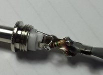
The CM GT does not have a volume control, so you need to reduce the input level a LOT. I used a 1 Megohm resistor in the 1/4 stereo plug (see photo) This was sufficient for the Simple Transmitter but this one runs on 3v and has less head room so it needed to be reduced more. I added a 25000 ohm multi turn trimmer next to the board (see photo yellow wires are input from shielded cable to trimmer to board. To get an idea of the input level you can use a VOM to measure AC voltage coming from the MD with a constant tone such as pinpointing or overlaod.. about .3-.4 volts AC is all you need for this Transmitter.
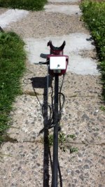
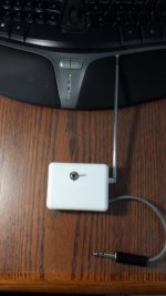
With just a wire for an antenna you will get about 5-8' of range. I went to Radio Shack and bought their replacement mast antenna and with the mast collapsed I now get about 30 ft which is sufficient to move around your MD without getting static in your ears as soon as you step away.
Here is a link to the BA1404 kit. http://electronics-diy.com/store.php?sel=kits&sub=fm_transmitters
This site does not respond to email, and I was kind of skeptical if I would get the kit and if it would be complete. Ordered it on a Friday, arrived the following Monday. Checked the parts list and all was accounted for. I did find out as I assembled it, on capacitor (C5) is not on the parts list but was present.
The instructions are one page, it assumes you have built kits before and have the basic skills to look a the board marking and the pictures that are included. It is not step by step.
The only thing I ran into is that the carrier leaks a bit on this IC and causes a rolling sine wave tone that is rather annoying. The data sheet for the BA1404 IC talks about adding var pots to fix this, but a .001uf Disc Cap (code stamp 102) the + and - of one of the inputs ( I put it on the left as it was easy to get to you can see it in the lower left hand corner)
took care of it completely.
Input from my Coinmaster GT is mono so both inputs are tied together and sent to both left and right + connections on the board. The ground only need to attached to one - as it is common.
The CM GT does not have a volume control, so you need to reduce the input level a LOT. I used a 1 Megohm resistor in the 1/4 stereo plug (see photo) This was sufficient for the Simple Transmitter but this one runs on 3v and has less head room so it needed to be reduced more. I added a 25000 ohm multi turn trimmer next to the board (see photo yellow wires are input from shielded cable to trimmer to board. To get an idea of the input level you can use a VOM to measure AC voltage coming from the MD with a constant tone such as pinpointing or overlaod.. about .3-.4 volts AC is all you need for this Transmitter.
With just a wire for an antenna you will get about 5-8' of range. I went to Radio Shack and bought their replacement mast antenna and with the mast collapsed I now get about 30 ft which is sufficient to move around your MD without getting static in your ears as soon as you step away.