
Billvert
Elite Member
Here are a few photos for those of you who may be thinking about repairing, modifying or are just generally curious about what is inside the flashy yellow box.
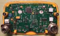
1.) View of main board with front panel removed.
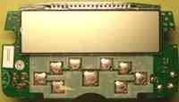
2.) LCD and Front panel Switch pads.
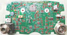
3.) Top of PC board with component placement. You may enlarge and compare to schematic to obtain component values.
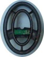
4.) Coil impedance matching network.
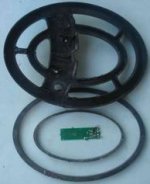
5.) Transmit (larger) and receive coils.
6.) Schematic.
7.) Coil Jack pin-out and matching network.
These photos should all have sufficient resolution to enlarge and be easily read.
Disclaimer: The information contained within this post is for recreational purposes only. Opening and/or modifying your detector will void the warranty. All information contained in my post is readily available on the internet and assumed to be public and non propriety. Use at you own risk.
1.) View of main board with front panel removed.
2.) LCD and Front panel Switch pads.
3.) Top of PC board with component placement. You may enlarge and compare to schematic to obtain component values.
4.) Coil impedance matching network.
5.) Transmit (larger) and receive coils.
6.) Schematic.
7.) Coil Jack pin-out and matching network.
These photos should all have sufficient resolution to enlarge and be easily read.
Disclaimer: The information contained within this post is for recreational purposes only. Opening and/or modifying your detector will void the warranty. All information contained in my post is readily available on the internet and assumed to be public and non propriety. Use at you own risk.

 BTW, the PCB was very obviously designed for several models so its entirely possible it could be easily converted to another, or at minimum features from higher models could be easily added, coil frequency changed, discrimination fine-tuned, much more.
")