Modifying a Wizard II

Spookydad

Full Member
Joined
Jul 19, 2007
Messages
109
Location
Houston TX
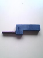
I decided to see if I could modify the wizard II to be more useful. I opened it up and discovered the coil is removable. I thought if I turned it 90 degrees and placed it in a tube, it would work better. The only thing is that doesn't gain much depth.

For those of you with an electrical background, would splicing in some extension wire to the coil change the readings? I know that tiny coated wire is a pain to solder.

There seem to be two different windings. A longer one (copper coloured) and a shorter one (red). Any idea why? Which end would be better to put towards the tip? I would like to put an 8" tube on the end.

SpookyDad

wizard.jpg
 
When I make my probes I go for the end with the most windings ( in your case the gold ) but a simple test near each end will find the best.

Best of luck. Heres a shot of my latest with a buzzer.
 

Attachments

  • picture00013.jpg
    picture00013.jpg
    10.1 KB · Views: 1,660
Even your MD "coil" has two coils. One is the transmitter and one is the receiver. Usually the larger coil is the transmitter. So I imagine yours should work best horizontally with the junction of the two coils being the hot spot, which doesn't look like it would be in the center line of the pinpointer.

How long were you wanting to extend the wires? Extending them should not be an issue if not too long. The more length of wire, the more resistance. The more resistance, the less current. And the less current, the less the magnetic field. A few more inches of length will not be a factor. But several feet probably would be.

When soldering the wires, just use some flux paste on the section of wire you want the solder to stick to if you are having problems. Also, the coloring of the wire is actually an insulating coating. This insulator would need to be carefully scraped off to reveal the shiny copper conductor before fluxing and soldering. Once the insulator is removed, though, you shouldn't need the flux. The wire is pretty fine and will easily heat up enough for the solder to adhere. Make sure to use thin, flux-core, electronic type solder, not the fat stuff used for plumbing.

HTH
 
Well I finished reconfiguring it. If anything it does appear to be a little more sensitive now.

SpookyDad

modifiedwizard.jpg
 
Thats a neat job spookydad. Is that tape you have wound around it?

If so probably find in time it will come off. May I suggest coating it in

something to keep any moisture out.One of the best Ive seen on here. Most

of them resemble a box with a flimsy rod on the side!!! Glad you have not

gone down that road, and have made a nice little compact unit with the

probe on the end (where it belongs! )

WELL DONE. Hope you locate many good finds with it.
 
Thanks.

It is tape and it will proably come off. It is more for looks than anything else. The joints are assembled with hot glue for strength and to seal out moisture. The bulges at the joints are pieces of styrene strips glued on for strength. It isn't pretty but it is functional. I was concered because the only thing attaching the tube to the body was the hot glue on the end of the tube. The coil is hot glued into the the end to keep it in place.

SpookyDad
 
Back
Top Bottom