pcboardnut
New Member
Hi friends of metal detecting. After reading about some bad reports about this unit that I also purchased from Heartland America, I decided to take a closer look by opening up the unit. I was fairly impressed about how easy it could be to work with the PC board and maybe make some improvements.
My detecting friends and I always wondered what it would be like to have more RF power output? We figured more power meant more detection depth. Well, that is sort of partly true. But, if you have read much about depth, you realize that a larger search coil will do just that. However, it has it's drawbacks concerning picking up the smaller objects.
I have successfully managed to make my detector crank out additional milliwatts. I know this because of my testing method. However, I did not break into the circuitry and measure the current flowing through the "two transistor" transmit system. As you may know, current times the voltage will indicate the input power of a transmitter. At first appearance from sketching out the transmit section, it looks very similar to a Darlington arrangement.
I did change out some resistor values and those changes allowed extra current to flow through Q5 and Q4. If you recall, adding resistors in parallel makes the total resistance less than the value of the smallest resistor. If the two resistors are each 100 ohms as an example, then the total resistance is half, or fifty ohms. When the values are unequal, there is an ohms law to calculate the total resistance. With this in mind, I used my Eico Model 1140 series-parallel R-C combination box for testing. The leads were equipped with hooked test clips. (I always liked to call them "J" clips).
I will include attachments showing photos and text to help anyone should you choose to soup up your GC-1019.
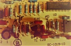
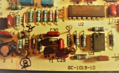
The original resistors on the board are placed right over the ID location, so it is practically impossible to see the "R" number. [R meaning resistor] and "C" meaning capacitor. The C numbers were pretty good.
I started working with R49 for no particular reason. But it was producing some gain. The selections were effecting the voltage on the sensitive base of Q5. Hindsight being what it is, I probably should have left the one meg ohm resistor in place. Too much soldering of parts in and out on the PC foil can get a person in trouble. Once done I decided to leave it. I used two resistors in series to get the value of 850 K ohms. The photo shows where I tied the top leads together.
Emitter resistor shown as ER-1 was bridged with the sub box, but I decided to leave it and work with what is now known to be R50. That R50 emitter resistor controlling the EC current flow through Q5 I knew would have a great effect on RF input power. The output at the collector of Q5 is directly driving the input base of Q4.
You could leave R49 as is and maybe work with the value of ER-1. If you would like to change R49 I would recommend 900K ohms. Leaving R49 in place, might even allow someone to have a value as low as 150 ohms for R50. You DON'T want to create a feedback from the transmit search coil into the receive coil. You'll hear it! It will go into oscillation.
So what happened as a result of these changes? I have discovered that I must lower the sensitivity settings on the detector to between 7 and 10. With a setting of 9 using notch, a penny sounded off between seven and eight inches from the search coil. [Note: This was an open air test with the detector search coil hovering out beyond the edge of the table.] I get about the same result using a dime. I believe this is what is going on. Earlier, I used to set the sensitivity as high as twelve out in the field. Due to the receive coil being only inches from the transmit coil, I now think the extra power is de-sensing the receiver if the sensitivity is set too high. This would be similar to what happened with my 2 meter amateur communication when two vehicles are too close together, especially when one is using a 40 watt class "C" amplifier.
Of course this extra boost in power is not free. You would need to expect a shorter battery life. Personally, I like to use the Energizer advanced lithium nine volt types. I even break the rules and give them some recharging with my Radio Shack deluxe charger that I purchased many years ago. When they are totally exhausted, that's when they go to the recycle center
Resistance measurements were made using my Heathkit IM-2215 and also a Centec item # 98025 digital multimeter. The de-soldering was made easy using my new Tenma 21-8240 from MCM Electronics [now element 14]. I also used an analog multimeter. I still like those analog meters.
Good luck if you do this project.
My detecting friends and I always wondered what it would be like to have more RF power output? We figured more power meant more detection depth. Well, that is sort of partly true. But, if you have read much about depth, you realize that a larger search coil will do just that. However, it has it's drawbacks concerning picking up the smaller objects.
I have successfully managed to make my detector crank out additional milliwatts. I know this because of my testing method. However, I did not break into the circuitry and measure the current flowing through the "two transistor" transmit system. As you may know, current times the voltage will indicate the input power of a transmitter. At first appearance from sketching out the transmit section, it looks very similar to a Darlington arrangement.
I did change out some resistor values and those changes allowed extra current to flow through Q5 and Q4. If you recall, adding resistors in parallel makes the total resistance less than the value of the smallest resistor. If the two resistors are each 100 ohms as an example, then the total resistance is half, or fifty ohms. When the values are unequal, there is an ohms law to calculate the total resistance. With this in mind, I used my Eico Model 1140 series-parallel R-C combination box for testing. The leads were equipped with hooked test clips. (I always liked to call them "J" clips).
I will include attachments showing photos and text to help anyone should you choose to soup up your GC-1019.
The original resistors on the board are placed right over the ID location, so it is practically impossible to see the "R" number. [R meaning resistor] and "C" meaning capacitor. The C numbers were pretty good.
I started working with R49 for no particular reason. But it was producing some gain. The selections were effecting the voltage on the sensitive base of Q5. Hindsight being what it is, I probably should have left the one meg ohm resistor in place. Too much soldering of parts in and out on the PC foil can get a person in trouble. Once done I decided to leave it. I used two resistors in series to get the value of 850 K ohms. The photo shows where I tied the top leads together.
Emitter resistor shown as ER-1 was bridged with the sub box, but I decided to leave it and work with what is now known to be R50. That R50 emitter resistor controlling the EC current flow through Q5 I knew would have a great effect on RF input power. The output at the collector of Q5 is directly driving the input base of Q4.
You could leave R49 as is and maybe work with the value of ER-1. If you would like to change R49 I would recommend 900K ohms. Leaving R49 in place, might even allow someone to have a value as low as 150 ohms for R50. You DON'T want to create a feedback from the transmit search coil into the receive coil. You'll hear it! It will go into oscillation.
So what happened as a result of these changes? I have discovered that I must lower the sensitivity settings on the detector to between 7 and 10. With a setting of 9 using notch, a penny sounded off between seven and eight inches from the search coil. [Note: This was an open air test with the detector search coil hovering out beyond the edge of the table.] I get about the same result using a dime. I believe this is what is going on. Earlier, I used to set the sensitivity as high as twelve out in the field. Due to the receive coil being only inches from the transmit coil, I now think the extra power is de-sensing the receiver if the sensitivity is set too high. This would be similar to what happened with my 2 meter amateur communication when two vehicles are too close together, especially when one is using a 40 watt class "C" amplifier.
Of course this extra boost in power is not free. You would need to expect a shorter battery life. Personally, I like to use the Energizer advanced lithium nine volt types. I even break the rules and give them some recharging with my Radio Shack deluxe charger that I purchased many years ago. When they are totally exhausted, that's when they go to the recycle center
Resistance measurements were made using my Heathkit IM-2215 and also a Centec item # 98025 digital multimeter. The de-soldering was made easy using my new Tenma 21-8240 from MCM Electronics [now element 14]. I also used an analog multimeter. I still like those analog meters.
Good luck if you do this project.